Hi quest ,  welcome  |  sign in  |  registered now  |  need help ?

Definition List

Flag Counter

Hot Bend and How it's Made

Written By pipeline-engineer.com on Saturday, May 16, 2020 | 10:56:00 AM


Induction Bending is a controlled means of bending pipes through the application of local heating using high frequency induced electrical power.


Originally used for the purpose of surface hardening steels, induction technology when used in pipe bending consists basically of an induction coil placed around the pipe to be bent. The induction coil heats a narrow, circumferential section of the pipe to a temperature of between 850 and 1100 degrees Celsius (dependant on the material to be formed). As the correct bending temperature range is reached, the pipe is moved slowly through the induction coil whilst the bending force is applied by a fixed radius arm arrangement.


Manufacture of Induction Bends

Induction bends are formed in a factory by passing a length of straight pipe through an induction bending machine. This machine uses an induction coil to heat a narrow band of the pipe material. The leading end of the pipe is clamped to a pivot arm.

As the pipe is pushed through the machine, a bend with the desired radius of curvature is produced. The heated material just beyond the induction coil is quenched with a water spray on the outside surface of the pipe. Thermal expansion of the narrow heated section of pipe is restrained due to the unheated pipe on either side, which causes diameter shrinkage upon cooling.

The induction bending process also causes wall thickening on the intrados and thinning on the extrados. The severity of thickening/thinning is dependant on the bending temperature, the speed at which the pipe is pushed through the induction coil, the placement of the induction coil relative to the pipe (closer to the intrados or extrados), and other factors.


Most induction bends are manufactured with tangent ends (straight sections) that are not affected by the induction bending process. Field welds are made or pipe pup sections are attached to the unaffected tangent ends, allowing for fitup similar to that found when welding straight sections of pipe together.


Induction bends come in standard bend angles (e.g. 45°, 90°, etc.) or can be custom made to specific bend angles. Compound bends (out-of-plane) bends in a single joint of pipe can also be produced. The bend radius is specified as a function of the diameter. For example, common bend radii for induction bends are 3D, 5D and 7D, where D is the nominal pipe diameter.


Benefits of Induction Bends

  • Large radii for smooth flow of fluid.
  • Cost efficiency, straight material is less costly than standard components (e.g. elbows) and bends can be produced faster than standard components can be welded.


  • Elbows can be replaced by larger radius bends where applicable and subsequently friction, wear and pump energy can be reduced.
  • Induction bending reduces the number of welds in a system. It removes welds at the critical points (the tangents) and improves the ability to absorb pressure and stress.


  • Induction bends are stronger than elbows with uniform wall thickness.
  • Less non-destructive testing of welds, such as X-ray examination will save cost.
  • Stock of elbows and standard bends can be greatly reduced.
  • Faster access to base materials. Straight pipes are more readily available than elbows or standard components and bends can almost always be produced cheaper and faster.

  • A limited amount of tools is needed (no use of thorns or mandrels as required in cold bending).
  • Induction bending is a clean process. No lubrication is needed for the process and water needed for the cooling is recycled.


ASME B16.49

ASME B16.49 Standard covers design, material, manufacturing, testing, marking, and inspection requirements for factory-made pipeline bends of carbon steel materials having controlled chemistry and mechanical properties, produced by the induction bending process, with or without tangents.


This standard covers induction bends for transportation and distribution piping applications (e.g., ASME B31.4, B31.8, and B31.11). Process and power piping have differing requirements and materials that may not be appropriate for the restrictions and examinations described herein, and therefore are not included in this Standard


10:56:00 AM | 0 comments

Talking About Pig Launcher and Receiver

Written By pipeline-engineer.com on Monday, March 23, 2020 | 6:15:00 AM

Variety of applications, locations and product types of Pig Launcher and Receiver, along with a wide array of designs – some good, some bad, natural gas and liquid pig launchers and receivers should differ in design but share some common features. Certain applications require specially designed units. For example:
  • Offshore sites where space is limited, and vertical units are more suitable.
  • Wet gas gathering systems when lines may need to be pigged several times a day or week to remove liquids. Automating these units saves manpower, reduces gas releases, cuts valves maintenance cost, and addresses safety concerns.
PIG Launcher & Receiver

Some companies attempt to design a combination pig launcher and receiver unit to perform both functions. This can be done. However, it is costly, complicates the launching and receiving process and very few pipelines flow bi-directionally.


Launching and receiving pigs is not as simple as some people think. You are venting or draining high-pressure gas or liquids, which requires certain valves to be opened and closed in the proper sequence. A quick opening closure must be opened to allow access to either the launcher or receiver for insertion or removal a pig. At this point, an explosive environment has been created and often the valves isolating the unit are leaking slightly.
What are the key considerations when building pig launchers and receivers?
1) Purpose of pigging – Pipelines are normally pigged for one or more of the following reasons:
  • Cleaning: To improve flow efficiency or reduce internal corrosion.
  • Displacement: To displace the line contents.
  • Batching: To separate different products within an operating pipeline.
  • Inline inspection: To perform an internal inspection with an inline inspection (ILI) tool for integrity purposes.
One must establish a need to pig a pipeline before investing in the installation and operation of a pig launcher and receiver.
2) Size – A typical designation for pig launchers/receivers would be:
  • 10-inch by 12-inch 300# pig launcher or pig launch system
    • This would indicate a launcher for a 10-inch pipeline with a 12-inch oversize barrel that allows the operator to slide the pig into launch position. The maximum operating pressure could be 740 psi. The word “system” generally implies that all valves and associated piping are included.
  • 20-inch by 24-inch 600# pig receiver or pig receive system
    • This would indicate a receiver for a 20-inch pipeline with a 24-inch oversize barrel and could have a maximum operating pressure of 1480 psi.


We recommend the oversize barrel be one size larger than the pipe size for pipe diameters up to 10-inch (i.e., 6-by-8, 10-by-12). On any pipe size of 12 inches or larger, the barrel size should be at least two pipe sizes larger (such as 16-by-20, 20-by-24). An odd sized barrel would be a reason to increase the barrel size to the next readily available pipe size, such as 24-by-30.


3) Length – The launcher or receiver length is determined by the type of pigs used. Today, most launchers and receivers are designed to accommodate the length of an ILI tool. A unit long enough for an ILI tool is certainly a sufficient length for cleaning, batching, and displacement pigs. The ILI tools have gotten longer due to multi-data set technologies. Each section of an ILI tool collects different types of data, which provides detailed information on the integrity of the pipeline. As a rule of thumb, we consider an ILI tool to be 15 feet long on average. Therefore, the oversize barrel should be slightly longer than 15 feet and the receiver should have a length of line size pipe to ensure the ILI tool has cleared the mainline trap valve. A receiver designed to handle an ILI tool will need to be over 30 feet long. The launcher can be shorter due to the line size portion being 8 feet to 10 feet shorter. If the pipeline is not to be designed for ILI tools, the length of the launcher and receiver can be reduced accordingly. Cleaning, batching, and displacement pigs are approximately two pipe diameters in length. Receivers should be designed to be long enough to hold at least two pigs.


4) Pressure rating – Launchers and receivers are normally designated to a flange rating of 300#, 600#, 900#, etc. However, the actual working pressure and test pressure are determined by the operating conditions and design code of the pipeline system. Most operators will designate the Max Operating Pressure (MOP) and set a pressure rating to which the launchers and receivers are to be designed. We recommend the design factor be at least 0.5 since launchers and receivers see multiple pressure cycles throughout their lifetime that the pipeline does not experience.
5) Launcher design vs. receiver design – We have already discussed why the launcher is generally shorter than the receiver. The launcher and receiver have the same number of nozzles but differ in location for a variety of reasons. The launcher should have a “kicker line” located near the closure, allowing flow to be directed behind the pig for a successful launch. This “kicker line” is normally sized one-third to one-half the size of the pipeline. A 12-inch pipeline would have a 4-inch to 6-inch kicker line. For a 12-inch line, we recommend a 6-inch kicker on a natural gas pipeline and a 4-inch kicker on a liquid pipeline. On the receiver, we call this line the “receiver bypass line.” This line should be located near the reducer entering the oversize barrel. This location allows the flow to exit the receiver without the pig interrupting the flow, space for the pig to come to rest in the oversize barrel without striking the closure door and easy retrieval.
Both launchers and receivers should have a vertical vent line above head height located near the closure and a pressure gauge connection near the closure allowing the operator to view the line pressure within the unit. Liquid units should have a drain system that allows the liquid to drain into a sump tank. This drain system on the receiver should have a minimum of two drain connections in front of and behind where the pig comes to rest. This prevents the drains from being blocked by the pig and allows the entire barrel to be drained. These vents and drains should be appropriately sized to allow for the venting and draining to be achieved in a reasonable timeframe. It is not ideal to drain a 36-inch by 40-inch receiver through a 2-inch drain. The other crucial nozzles on both the launcher and receiver are the equalization lines. These lines allow the pressure and product to be filled, vented and equalized on either side of the pig. The loading of long and heavy ILI tools can be difficult because the tools have flexible joints with several sections. These tools can be loaded using a tray or a system of nozzles and cables to assist with loading. Pig indicators are critical in determining if the pig has been launched or received and must be installed in the correct position. The pig indicator on the launcher should not be installed on the launch barrel but downstream of the mainline bypass tee. The pig indicator on the receiver should be installed on the line size pipe near the reducer on the receiver barrel. Pig indicators are a critical component; we recommend that two be installed at each location for redundancy, should one fail.


6) Launcher/receiver systems vs. launcher/receiver barrels – The term “system” indicates the unit includes all valves and associated piping. Systems are normally skid mounted, and a completed pigging system requires two major field tie-ins to put it in service. The system is hydro-tested as a complete unit and functionally tested prior to delivery. The site is usually prepared by pouring concrete piers to support the skid weight, then set into position, then bolt connected to the inlet and outlet. This saves a tremendous amount of field installation cost. This also allows for easy access to all the major components for future maintenance needs. A launcher/receiver barrel does not include the valves, piping and skid mounted assembly, which must be assembled, fabricated and tested in the field. Complete pigging systems will save money in the short- and long-term and, if necessary, can be relocated.


7) Product type – Gas launchers and receivers differ from liquid launchers and receivers for some of the same reasons. The primary differences are:
  • Design Code (ASME B31.8 Gas vs. ASME B31.4 Liquid)
  • Drains and sump tanks are required on liquid launchers and receivers and may also be needed on gas receivers when handling liquids.
When pig launchers and receivers are designed correctly, the benefits you receive are: 
  • The right design has safety features that eliminate accidents.
  • The right design reduces operation and field installation cost.
  • The right design eases the launching and receiving process.
  • The right design allows for consistency in launching and receiving procedures and operator qualifications.
  • The right design assures the unit complies with applicable codes and standards.


6:15:00 AM | 0 comments

Lagos Gas Explosion Destroys Buildings & Fatalities number hit 15 peoples

Written By pipeline-engineer.com on Tuesday, March 17, 2020 | 12:46:00 AM


LAGOS (Reuters) — An explosion at a gas processing plant on Sunday killed at least 15 people and destroyed about 50 buildings after a fire broke out in a suburb of Lagos, Nigeria's commercial capital, emergency services said.


The Nigerian National Petroleum Corporation (NNPC) said the explosion was triggered after a truck hit some gas cylinders stacked in a gas processing plant near the corporation's pipeline in Abule Ado area of Lagos state.


The impact of the explosion led to the collapse of nearby houses, damaged NNPC's pipeline and caused the corporation to halt pumping operations on the Atlas Cove-Mosimi pipeline, the state-owned oil company said in a statement.


Several people were injured and taken to hospital, according to Ibrahim Farinloye, zonal coordinator for the National Emergency Management Agency (NEMA).
Plumes of smoke billowed into the air as people watched, while firefighters tried to quench the flames, a Reuters witness said.


Farinloye told Reuters that "the explosion destroyed over 50 residential houses."
Pipeline fires in Nigeria, Africa's biggest crude oil producer, are common and they are mostly caused by theft and sabotage. The methods used to steal oil often result in accidents that cause fires.


"The fire started with smoke," one eyewitness said. "The smoke was coming up and later we heard a sound ... and some houses collapsed even the roofs."
NNPC said that the temporary shutdown of the petroleum products pipeline would not affect the normal supply of products to the Lagos and surrounding towns.
12:46:00 AM | 0 comments

Cano Limon pipeline Stop Operating after a bomb attack

Written By pipeline-engineer.com on Wednesday, February 19, 2020 | 9:12:00 PM

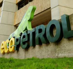
BOGOTA (Reuters) - Colombia's state-run oil company Ecopetrol has halted pumping on its Cano Limon pipeline after a bomb attack in the country's northeast caused a fire and spillage of crude into waterways.
The attack took place on Tuesday afternoon in Toledo municipality in Norte de Santander province, which borders Venezuela, Ecopetrol pipeline subsidiary Cenit said in a statement on Wednesday.
"The attack produced a rupture in the pipeline, a fire and the falling of crude into the La Petra ravine and the Sararito and Margua rivers," Cenit said.
There were 71 attacks on Colombian pipelines in 2019, down 33.6% from the year before.
The 480-mile (770-km) Cano Limon is a top target for bombings; it has suffered eight attacks so far this year and weathered 42 in 2019, according to Ecopetrol.
The attack has not affected exports or work in the Cano Limon oilfield, which is operated by Occidental Petroleum , because crude can also be transported on the mostly underground Bicentenario pipeline.
Although Cenit did not name the group responsible for the bombing, an army source in the region said leftist National Liberation Army (ELN) rebels, considered a terrorist organization by the United States and the European Union, were responsible.
The 2,000-strong ELN regularly attacks oil infrastructure.
9:12:00 PM | 0 comments

First time in a decade global oil demand expected to drop


LONDON (Bloomberg) - Global oil demand will drop this quarter for the first time in over a decade as the coronavirus batters China’s economy, the International Energy Agency said.
The new estimates show that oil markets face a significant surplus despite the latest production cuts by OPEC and its partners. Crude already sank to a one-year low below $50 a barrel last week and the impact of the epidemic will be felt throughout the year, the agency said.

“Demand has been hit hard by the novel coronavirus and the widespread shutdown of China’s economy,” the Paris-based IEA said. “The crisis is ongoing and at this stage it is hard to be precise about the impact.”
World fuel consumption -- which had previously been expected to grow by 800,000 barrels a day during the three-month period, compared with a year earlier -- will instead contract by 435,000 a day, the IEA said in its monthly oil market report.
For 2020 as a whole, the virus will curb annual growth in global consumption by about 30% to 825,000 barrels a day, the lowest since 2011. The effects will be more significant than those of the 2003 SARS epidemic because of China’s increased importance and integration within the world economy.
The outbreak has shuttered businesses and prompted the quarantine of tens of millions of people in China, the world’s biggest crude importer. The country accounted for about 75% of last year’s oil-demand growth, according to the IEA, which advises most major economies.
Earlier this week, the U.S. Energy Information Administration also cut its demand outlook due to the virus. The EIA lowered its first quarter global petroleum and liquids consumption forecast by 880,000 barrels a day.
U.S. crude futures have fallen 17% this year as traders assessed the impact of the epidemic. Consumers are unlikely to benefit from the drop in fuel prices because the disease will inflict damage on the wider economy, the IEA said.

The outbreak has prompted Saudi Arabia, the world’s largest oil exporter, to push its allies in the Organization of Petroleum Exporting Countries and beyond to consider an emergency meeting and further production cuts. However, Russia, the kingdom’s most important partner in managing supplies, has so far resisted the initiative.

Even though the group launched new supply curbs at the start of this year, the slump in demand threatens markets with a surplus of about 1.7 million barrels a day during the first quarter and 560,000 in the second. Last month, OPEC was already pumping the least crude since the financial crisis of 2009, according to the IEA.

The OPEC+ alliance had already faced an oversupply in the first half of 2020 because of the ongoing output surge from U.S. shale-oil drillers, the agency said. That industry is likely to remain resilient against the price slump until later in the year, it predicted.
Given the abundance of supply, disruptions in OPEC members such as Libya and Nigeria are having little impact on prices, the agency said.

9:03:00 PM | 0 comments

Ask Wikipedia

Search results

Subscribe to Pipeline-Engineer.com

Adsspace 140x140

Site Links

Blog Archives

Total Pageviews

Recommended Books

Recommended Books